- Home
- >
- News
- >
- Industry News
- >
- Overview of locking ring Closure
Overview of locking ring Closure
1.1 Rsearch background and process of locking ring Closure
Our factory is one of the first batch of manufacturers able to independently produce quick opening Closures, and has a history of over 10 years; during this period, the company has adhered to the operating principle of "quality first, customer orientation, continuously promoting satisfaction projects, and provding owners with high-quality products and services", and has achieved continuous product innovation. The company has been in good standing so far, without any fault record.
In July 2008, Shenyang Yongye Industry Co., Ltd. set up a special technical team in accordance with the status quo when domestic large-diameter and high-pressure quick opening Closures depended on imports. The main design mode of the quick opening Closure in the country’s design specification for quick opening Closure SY/T0556 was insert-plug and clamp button at that time. Such two Closures, compared with the structures of foreign advanced quick opening Closures is of complex structure and bulky, with many opening mechanism accessories and especially large manually operated load, and it is very laborious to open and turn off them in use. Since the Closure with its own structural defects was no longer able to meet the actual need, the company's technicians on the basis of drawing on foreign products, developed DN800 PN7.0MPa locking ring quick opening Closure for eight months. It has an advanced structure and reliable sealing, easy to manually operate, and reasonable strength reserve, and safety in use. What’s more, it was successfully applied in October 2009 in the extension line project of Sichuan to East Gas Transmission from Changshou to Fuling Nanchuan, and a 56-inch Class600 quick opening Closure was successfully manufactured for a Sinopec overseas project in July 2012.
The successful research and development of this locking ring Quick Opening Closure markes that it has been mature in the large-diameter and high-pressure quick opening Closure with independent intellectual property and in achieving localization. A utility model patent was applied for it in May 2010, and it was granted a patent (patent number: ZL 2010 2 0205038.X) in March 2011.
1.2 Performance description of the locking ring Closure
1.2.1 Technical Parameters
Design pressure: 1.6MPa-30MPa.
Test pressure: water pressure is 1.5 times the design pressure, and air tightness test is equivalent to the design pressure.
Working media: oil, natural gas, water, ore pulp, etc.
Corrosion allowance: 2mm.
Seismic fortification intensity: 7 degrees.
Opening time: less than 60 seconds (not over 200N force).
Life of sealing ring: ≥2 years.
1.2.2 Technical Features
1 Structural features
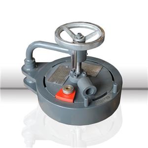
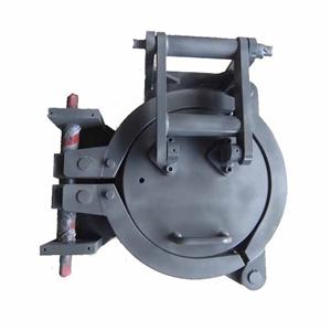
As for the locking ring Closure, our company can now design and produce two structural forms of Closures, which are inner locking ring Closure and outer locking ring Closure. Each structural form of Closure can be classified into vertical type and horizontal type.
Before pressing, when a Closure cover is sent to the cylinder flange (with a long-necked flange) in place, the locking ring is open, the insert can be placed inside the cylinder flange groove and locking ring gap, and the alarm screw can be screwed to achieve sealing of the safety interlocking device, when the device can be pressurized; otherwise, the device will not boost.
Before the device is boosted, the quick opening Closure and its locking mechanism can be both locked on a predetermined operating part, and the device can not boost if they fail to reach the predetermined locking position;
After the device pressure relief, and before t opening he Closure cover, slowly release the alarm screw, and the alarm screw will whistler if there is residual pressure, when tightening the screw alarm, re-checking the device status, waiting until there is no residual pressure before opening again, thus avoiding security risks arising from misuse.
1.2.3 Research and development and improvement of the sealing ring
Its unique lip self-storage sealing structure makes the sealing more secure and pretightening force smaller.
Long life of the sealing ring: more than 3 years
Sealing ring is made from fluorine rubber, nitrile rubber and other materials through the company's own mold manufacturing according to the actual situation.
The temperature suitable for the sealing ring is generally: -40 ~ 200℃.
1.2.4 Performance Indicators
Physical indicators of fluorine rubber lip ring
Material | Ozone resistance | Heat resistance | Chemical resistance | Oil resistance | Cold resistance | Mechanical | Tension strength | Deformation resistance | Steam resistance |
fluorine rubber | Particularly good | 240℃ | Particularly good | Particularly good | -40℃ | Good | Particularly good | Good | Ordinary |
1.2.5 Design of locking-ring quick opening Closure
1.The locking ring quick opening Closure is designed using the method of finite element analysis
Cloud chart of Closure stress intensity
As can be seen from the chart, the contact stress on the locking ring with the cylinder and flush cover is maximum.
2. Evaluation method for stress intensity
Elastic stress analysis and plastic failure criteria, and elastic-plastic failure criteria are basic design methods; the provisions on selection, fabrication, inspection and acceptance are more stringent than the requirements of GB150 steel pressure vessel.
Strength evaluation of the structure of each part of the Closure
The stress distribution and size of the structure of each part of the Closure are obtained using the method of finite element analysis. According to the provisions of JB4732-95, in stress classification, the components with the nature of secondary stress are incorporated into primary local film stress, and the safety of various parts of the Closure is evaluated.
2.Nomenclature of outer locking ring Closure
Drawing No.: WSMB nominal diameter, installation form L/W – engineering pressure -00
Example: DN700 outer locking ring Closure used on the vertical device, with a nominal pressure 5.0MPa
Drawing No.: WSMB700L-50-00
Name: vertical outer locking ring Closure DN700-PN50
If it is not a standard nominal pressure, a pressure level rounded up to the standard pressure level can be selected in terms of drawing number, but the required pressure level should be adopted for the name.
Example: DN700 outer locking ring Closure used on the horizontal device, with a nominal pressure 4.4MPa
Drawing No.: WSMB700W-50-00
Name: Horizontal outer locking ring Closure DN700-PN44
Nominal diameter DN(mm) | Horizontal | Vertical | h Sealing surface to cylinder end surface | D | D1 | D2 | Mass of Closure | ||
L1 | H1 | L2 | H2 | kg/set | |||||
400 | 650 | 410 | 640 | 700 | 220 | 540 | 426 | 280 | |
450 | 700 | 430 | 690 | 780 | 240 | 590 | 457 | 385 | |
500 | 770 | 450 | 850 | 840 | 260 | 650 | 529 | 450 | |
600 | 860 | 490 | 940 | 860 | 265 | 740 | 600 | 600 | |
650 | 940 | 510 | 990 | 920 | 280 | 790 | 650 | 780 | |
700 | 1010 | 530 | 1060 | 970 | 300 | 860 | 700 | 920 | |
800 | 1120 | 580 | 1170 | 1060 | 320 | 970 | 800 | 1120 | |
900 | 1260 | 600 | 1260 | 1150 | 340 | 1060 | 900 | 1380 | |
1000 | 1330 | 710 | 1430 | 1210 | 350 | 1130 | 1000 | 2720 | |
1100 | 1500 | 800 | 1600 | 1300 | 360 | 1300 | 1100 | 3280 | |
1200 | 1800 | 880 | 1800 | 1380 | 365 | 1500 | 1200 | 3840 | |
1400 | 1980 | 940 | 1960 | 1600 | 370 | 1680 | 1400 | 5380 | |
1600 | 2170 | 1150 | 2170 | 1810 | 380 | 1870 | 1600 | 6920 | |
Note: The data in the table are for reference only. Should the design pressure or material be different, the size and weight will vary. If limited to the specifications listed in the table, we can design and manufacture the Closures separately beyond the scope of the table.